
When a fault appears on a circuit, everything that decides the outcome has already been decided, months earlier, on a drawing. The conductor was given a cross-section. The device was given a rating, a characteristic and a breaking capacity. The earthing system was given a return path. At the moment of the fault, those four choices are simply read out.
This note walks that moment, and explains what each of the four choices is answering. It assumes the ground covered in MCB curves and kA, in depth, the time–current characteristic, the B/C/D bands and the meaning of the kA figure, and builds on it rather than repeating it.
What a fault actually is
Three different events get discussed together, and separating them is the start of the whole subject:
- A short circuit, a low-impedance connection between live conductors, line to neutral or line to line. The current that flows is set almost entirely by the impedance of the supply and the cable, not by the load, so it is large and it arrives immediately.
- An earth fault, a connection between a live conductor and earth, or an exposed conductive part. The current here is set by the impedance of the whole earth-fault loop, which makes it a very different quantity from a short circuit, and the reason it needs its own treatment further down.
- An overload, not a fault at all. The circuit is intact and doing exactly what it was asked; there is simply more load on it than the conductor was sized for. It is a duty question, answered by the device's thermal element over minutes.
IS 732:2019 defines the first of these as the prospective fault current (clause 3.145): the overcurrent at a given point resulting from a fault of negligible impedance. The word that matters is prospective. It is a property of the installation at that point, present whether or not a fault ever occurs, and knowable in advance.
Why current becomes heat
Every conductor and every joint has resistance, and current through resistance deposits energy at a rate of I²R. Two consequences follow, and they behave quite differently.
Through the conductor, the quantity that matters is not current but current and time together, I²t, the energy let through during the event. A fault current many times the conductor's rating is entirely survivable if it lasts a few milliseconds, and the conductor is the same afterwards as it was before. The same current sustained is a different proposition. This is why every question in this article eventually becomes a question about time.
At a joint, the arithmetic is the same but the R is local. A termination that has loosened presents a small resistance in a very small volume, and it does so continuously under normal load, no fault required. That makes it the one heat source in an installation that no upstream device is watching, because nothing about it looks like an overcurrent. It is a workmanship question, and it is dealt with in its own section below.
The millisecond that matters
Between the fault appearing and the circuit being open, a protective device does three things in sequence. Its magnetic element responds to the rate and magnitude of the current and releases the mechanism. The contacts part, and an arc is drawn between them. The arc is driven into a stack of steel plates, the arc chute, which splits it, lengthens it, cools it and raises its voltage until it can no longer be sustained, and it extinguishes at the next current zero.
The useful consequence is that a device of this kind does not simply wait for the fault current to reach its peak and then interrupt it. By forcing the arc voltage up early, it opposes the current while it is still rising, so the actual current that flows is lower than the prospective current would suggest, and the energy let through is lower again, because that term is squared. This is current limiting, and it is the reason the let-through I²t of a device is a published figure in its own right, distinct from its rating and its curve.
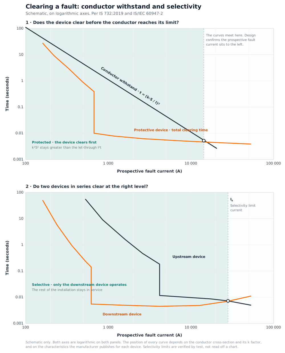
The upper panel of the chart above is that idea in its usual form: a conductor's withstand plotted against a device's total clearing time.
Why conductor size is a fault decision, not only a load decision
A conductor is usually sized from the load it carries continuously, with voltage drop and derating applied, the subject of a wire's two jobs. There is a second, independent question: can that same conductor absorb the energy of a fault for as long as the device needs to clear it, and still be within its permitted limit temperature afterwards?
IS 732:2019 answers it in clause 4.4.5.5.2 with the adiabatic equation. For faults of duration up to 5 s, the time for which a conductor can carry a given fault current is:
t = (k · S / I)²
where S is the conductor cross-sectional area in mm², I is the fault current in amperes, and k is a factor depending on the conductor material and its insulation.
For fast-acting and current-limiting devices, operating times below 0.1 s, which is where most short-circuit clearing sits, the standard states the condition directly: k²S² shall be greater than the let-through energy (I²t) quoted by the manufacturer of the protective device. That single line is the whole of the relationship. The left-hand side belongs to the cable. The right-hand side belongs to the device. Both are known numbers, and the design confirms one exceeds the other.
The k values come from IS 732:2019, Table 3. For thermoplastic PVC insulation at an initial temperature of 70 °C:
| Conductor | S ≤ 300 mm² (limit 160 °C) | S > 300 mm² (limit 140 °C) |
|---|---|---|
| Copper | 115 | 103 |
| Aluminium | 76 | 68 |
Two notes from the standard are worth carrying with those figures. The values change above 300 mm² because the permitted final temperature itself drops from 160 °C to 140 °C, the cross-section break is real, not a rounding. And Table 3 records that k values for cross-sections below 10 mm² remain under consideration, so 115 is a working figure rather than a precise one on a 1.5 or 2.5 mm² circuit. The factors are based on IEC 60724; the derivation is in IS 732 Annex EE.
What this reframes: an increase in cross-section raises the left-hand side by the square of the change. Cross-section is not only about carrying the load and holding the volt drop. It is also the term that decides how much fault energy the conductor can absorb without complaint.
Why the characteristic decides whether the device sees the fault
A device clears quickly when the fault current reaches its instantaneous magnetic threshold. Below that threshold it still operates, but on its thermal element, which is deliberately unhurried. So the design question is not whether the device will operate. It is whether the current available at that point is enough to put it in the fast region.
IS 732:2019 sets the times the answer has to meet. From Table 1, at the nominal line-to-earth voltage band that covers 230 V:
| Circuit | System | Maximum disconnection time |
|---|---|---|
| Final circuits | TN | 0.4 s |
| Final circuits | TT | 0.2 s |
| Distribution circuits | TN | 5 s |
| Distribution circuits | TT | 1 s |
The final-circuit figures are clause 4.2.11.3.2.2; the distribution-circuit allowances are clauses 4.2.11.3.2.3 and 4.2.11.3.2.4. Distribution circuits are given longer because they sit upstream, where a deliberate delay is what allows the device below to clear first, the subject of the last section.
This is where the choice of characteristic stops being about inrush and becomes about the fault current available. A curve that reaches its instantaneous region at a lower multiple of rated current will meet the disconnection time on a long run where the available current is modest; a curve that needs a high multiple wants a strong fault current to match. The in-depth note on curves sets out where each band belongs.
Why the device must also survive what it interrupts
Separate from the curve, and separate from the rating: the breaking capacity is the fault current the device can interrupt and remain intact. It answers a different question from everything above, not will it act, but will it come through the act.
IS/IEC 60898-1 lists the standard values of rated short-circuit capacity as 1 500, 3 000, 4 500, 6 000 and 10 000 A, with 20 000 A the preferred value above that. The rule is that this figure exceeds the prospective fault current where the device sits, highest at the origin, falling as cable impedance accumulates downstream.
One detail worth having, because it is often assumed to be a manufacturer's choice and is not. In IS/IEC 60898-1 the relationship between the ultimate capacity (Icn) and the service capacity (Ics, after which the device remains fit for continued service) is fixed by the standard, in Table 18:
| Rated short-circuit capacity Icn | Ics as a fraction of Icn |
|---|---|
| Icn ≤ 6 000 A | 1 |
| 6 000 A < Icn ≤ 10 000 A | 0.75, minimum 6 000 A |
| Icn > 10 000 A | 0.5, minimum 7 500 A |
So a 6 kA device has a service capacity of 6 kA, and a 10 kA device one of 7.5 kA, without anyone having to declare it. Moulded-case circuit-breakers under IS/IEC 60947-2 work the other way round: there the manufacturer declares Ics as one of 25, 50, 75 or 100 % of Icu, so it is a published specification that varies by product and is worth reading off the datasheet.
As for the prospective fault current itself, IS 732:2019 clause 4.4.5.1 is explicit that it shall be determined at every relevant point, by calculation or by measurement, and notes that the value at the supply point may be obtained from the supply utility. It is a figure to be established for the installation in question, not one to be assumed from typical practice.
Why earthing is what lets the protection work
Earthing is often filed under safety, alongside the things that protect people. It does that, but it also does something more structural: it is what makes an earth fault visible to the device in the first place.
IS 732:2019 clause 4.2.11.4.4 gives the condition for TN systems as:
Zs × Ia ≤ Uo
where Zs is the impedance of the fault loop, the source, the line conductor to the point of the fault, and the protective conductor back to the source; Ia is the current causing the device to operate within the required disconnection time; and Uo is the nominal line-to-earth voltage.
Rearranged, it reads Ia ≤ Uo / Zs, and in that form it says something plainly. The loop impedance sets a ceiling on the fault current available. The voltage is fixed. So the only variable that decides whether enough current can flow to put the device in its fast region is the impedance of the loop: the conductors, their length, their cross-section, the connections along the way, and the quality of the earth itself.
A loop kept low in impedance delivers a fault current well inside the device's instantaneous region, and the disconnection times in the table above are met with margin. That is what a good earth buys, and it is why earth resistance is the defining number of an earthing system rather than an incidental one. Where the loop impedance cannot deliver that current on its own, a residual current device answers the same requirement by a different route. It responds to the imbalance rather than to the magnitude, at currents far below anything an overcurrent device would act on. The note on RCCBs covers sensitivity, current rating and type. Note that where an RCD provides the disconnection, the standard's times relate to residual currents significantly above its rated operating current.
Where the chain is made at the point of work
Three of the four conditions are settled on a drawing. The fourth is settled at the terminal, and it is the one that quietly determines whether the other three hold.
- Terminations carry the loop. Every connection in the earth-fault loop adds impedance. A termination made to the manufacturer's torque figure contributes what the calculation assumed it would; one made by feel contributes an unknown. Torque figures exist for this reason, and a torque screwdriver is the instrument that honours them.
- Insulation carries the withstand. The k factor in the adiabatic equation is a property of intact insulation at its rated temperature. A conductor whose insulation was nicked during pulling is no longer the conductor the calculation described, which is why a damaged length is replaced rather than taped.
- Cross-sections carry the arithmetic. Protective conductors are part of Zs in exactly the way line conductors are. A protective conductor reduced for convenience raises the loop impedance and lowers the fault current available, and the disconnection time moves accordingly.
These habits, and the rest that go with them, are set out in good wiring workmanship. Work of this kind is done live-dead-live tested and de-energised, with correctly rated insulating gloves as standard practice.
Discrimination, clearing at the right level
A fault on one final circuit should open that circuit and nothing else. When the device immediately upstream of the fault operates and the ones above it do not, the arrangement is selective, and the rest of the installation stays in service. The lower panel of the chart shows the shape of it.
IS/IEC 60947-2 gives the definitions:
- Total selectivity, with two overcurrent devices in series, the load-side device provides the protection without causing the other to operate.
- Partial selectivity, the same, but only up to a given level of overcurrent.
- Selectivity limit current (Is), the current at which the downstream device's total operating characteristic meets the upstream device's tripping characteristic. Below it, selectivity holds; above it, both may operate.
Note that IS 732:2019 has no general clause on overcurrent selectivity, the framework sits in IEC 60364-5-53 clause 535, which distinguishes partial, full, total and enhanced selectivity, and in IS/IEC 60947-2 for the device definitions.
As a first-pass screen, manufacturers publish ratio guidance: a ratio of at least 2 between the setting currents for selectivity in the overload region, and at least 1.5 between the magnetic settings in the short-circuit region, with wider separation between ratings giving better results. These are design guidance from manufacturer literature, not requirements of any standard, no IEC or IS document mandates a numeric ratio.
The reason the ratios are only a screen is that selectivity between two specific devices under short-circuit conditions is established by test, and the results are published as selectivity tables and let-through curves for each device pairing. Those tables, and the coordination and cascading data that go with them, are what the pairing is confirmed against. They are available for the ranges we carry through the authorised channel, ask and we will point you to the current tables for the devices in question.
What we stock
Shreetuvis holds the protection ladder in Nagpur for trade supply, Hager and Legrand DX³ MCBs from 6 to 63 A in curves B, C and D at 6 kA and 10 kA breaking capacity, RCCBs and RCBOs, Hager h3+ MCCBs from 25 to 630 A, and distribution boards to house them. All ISI-marked to the relevant standard, see what the ISI mark certifies, and supplied genuine from the authorised channel. The Hager MCB page carries the range and the manufacturer's let-through data; send a circuit schedule or single-line diagram through the contact form for stock and project rates. For the devices individually: MCBs, RCCBs, surge protection, and earthing.