
The plain-language note on MCBs covers what the device does and how to read the letter and the number on its face. This is the engineer's companion: the time–current characteristic itself, how to read the curve, exactly where Types B, C and D each belong and where they fall short, and what the kA rating is for.
Reading the time–current curve
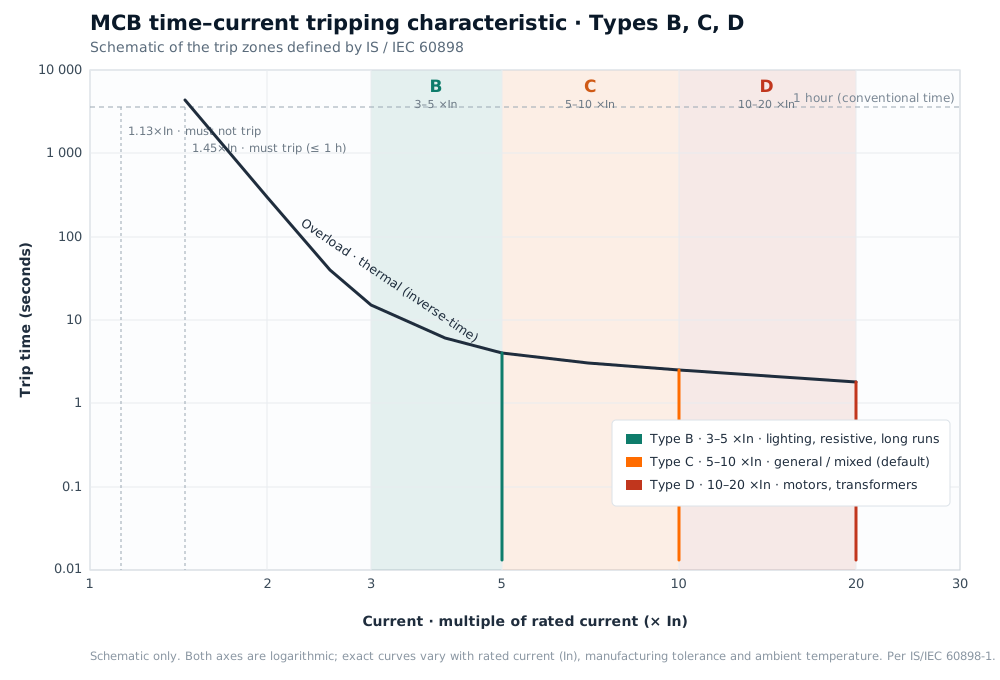
An MCB's behaviour is defined by a curve plotted on logarithmic axes: the multiple of rated current (× In) along the bottom, and the time to trip up the side. The curve has two regions, produced by two independent mechanisms inside the breaker:
- The thermal region (overload). A bimetallic strip heats and bends under sustained overcurrent, tripping on an inverse-time basis, the larger the overload, the sooner it trips. This is the sloping part on the left of the curve.
- The magnetic region (short-circuit). An electromagnetic coil reacts to a sudden, large fault current and trips almost instantly, typically within a few milliseconds. This is the near-vertical drop on the right.
Two further points. The characteristic is a band, not a single line, manufacturing tolerance and whether the breaker starts hot or cold shift the exact trip time. And the thermal region is essentially the same for B, C and D of a given rating; the only thing the type changes is where the magnetic region begins.
The thermal region, the IS gate points
IS/IEC 60898 pins the thermal characteristic to fixed test points, identical across the three types. These are the numbers the curve must honour:
| Test current | Required behaviour | Within |
|---|---|---|
| 1.13 × In | Must not trip | The conventional time (1 hour, for In ≤ 63 A) |
| 1.45 × In | Must trip | The conventional time (1 hour) |
| 2.55 × In | Must trip | Between 1 s and 60 s (for In ≤ 32 A) |
In plain terms, an MCB is expected to carry roughly 1.13 × its rating indefinitely and to clear a modest sustained overload within the hour. It is deliberately unhurried here, a brief overload, such as a few heavy appliances coinciding for a minute, should not trip a healthy circuit.
The magnetic region, where B, C and D differ
The type letter sets the current at which the instantaneous magnetic trip takes over. That is the entire difference between B, C and D:
| Type | Instantaneous trip | Built for |
|---|---|---|
| B | 3 – 5 × In | Resistive and low-inrush loads; long cable runs |
| C | 5 – 10 × In | General mixed loads, the everyday default |
| D | 10 – 20 × In | High-inrush loads, motors, transformers, capacitor banks |
Below its band the device can still trip, but only on the slower thermal element; at or above the upper figure it trips instantaneously. So the choice of type balances two things at once, the load's switch-on inrush, and the fault current available at that point in the installation.
B, C and D, where each belongs, and where it doesn't
Type B, 3 to 5 × In
- Suits: lighting, heating and other resistive loads with negligible switch-on surge, and, importantly, long cable runs and points with a low available fault current. Because B reaches its instantaneous trip at just 3–5 × In, it still clears a fault quickly even where a long, thin cable limits the fault current, which is what keeps the disconnection time inside the limit set by the earth-fault loop impedance.
- Where it doesn't suit: circuits with genuine inrush, motors, transformers, large banks of LED drivers or fluorescent fittings. Their start-up surge can briefly exceed 3–5 × In and trip a B curve with no fault present.
Type C, 5 to 10 × In
- Suits: the great majority of mixed domestic and commercial circuits, sockets, fans, air-conditioners, refrigeration, and lighting in normal quantities. The 5–10 × band absorbs ordinary inrush without nuisance tripping, which is why C is the default.
- Where it doesn't suit: at the two extremes. On a very long run with a low fault current, the fault may never reach 5 × In, so the breaker falls back on the slow thermal element and can miss the required disconnection time. There a B curve is the safer call. At the other end, a direct-on-line motor whose inrush tops 10 × In will nuisance-trip a C, which is the cue for D.
Type D, 10 to 20 × In
- Suits: high-inrush loads, direct-on-line motors, transformer primaries with their magnetising inrush, large capacitor banks, welding sets, X-ray equipment. The 10–20 × band rides through the brief, severe surge these loads draw at switch-on.
- Where it doesn't suit: a D curve needs a high available fault current, 10 to 20 × In, to trip instantaneously. On a circuit with a low fault level or a long run, that threshold may never be reached, so a fault would clear only on the slow thermal element; the design has to confirm the fault current and the earth-fault loop impedance are high enough. It is also needlessly insensitive on ordinary lighting and socket circuits, where B or C protects better.
The thread through all three: a lower type (B) trips on a smaller fault and is easier to satisfy on long, low-fault runs, but tolerates little inrush; a higher type (D) tolerates heavy inrush but needs a strong fault current to act instantaneously. C sits in the middle, which is why it is the everyday answer.
The kA rating, breaking capacity
The type and the rating describe how the MCB responds to overcurrent. The kA rating describes something separate: the largest short-circuit current the breaker can interrupt safely, clearing the fault without damage to itself. It is independent of the curve.
- Icn, rated short-circuit capacity. The headline figure, marked on the body inside a rectangle (for example 6000 or 10000, meaning 6 kA or 10 kA). It is the prospective fault current the breaker can interrupt under the standard's test conditions.
- Ics, service short-circuit capacity. The fault current after which the breaker is expected to remain fit for continued service. For these devices it is a defined fraction of Icn.
The rule is simply that the breaker's Icn must exceed the prospective fault current at the point where it is installed. That fault current is highest close to the source, at the incomer, near the transformer or the supply MCCB, and falls as cable impedance accumulates downstream. So a main or upstream MCB is commonly specified at 10 kA, while a breaker deep in residential sub-distribution may be safely served by 6 kA. Where an upstream device shares the duty, a documented back-up (cascading) coordination can let a lower-kA MCB sit behind a higher-rated breaker, but only where the manufacturer's tables confirm the pairing.
Specifying an MCB, in three independent choices
Put together, every MCB is three separate decisions:
- Rated current (In), set by the cable it protects, not the load beyond it.
- Type (B / C / D), set by the load's inrush and the fault current available at that point.
- Breaking capacity (kA), set by the prospective fault current where it sits.
Get those three right and the curve does the rest, exactly as the chart above describes.
What we stock
Shreetuvis stocks the full MCB ladder in Nagpur, Hager and Legrand DX³, across 6 to 63 A, curves B, C and D, breaking capacities of 6 kA and 10 kA, and single- to four-pole, ISI-marked to IS 8828 (see the ISI mark) and supplied genuine from the authorised channel. See the Hager MCB page for the range, or send a circuit schedule through the contact form for stock and project-rate pricing. For the plain-language version, see MCBs, the switches in your board; the device that partners it on every board is the RCCB.